
Where the Heat Goes
Air cooling lost to arithmetic. To carry the heat of one modern AI rack away with air, you would have to move dozens of bathtubs' worth of air through it every second. Water does the same job through a pipe you could wrap your hand around. Once racks crossed the 100 kW line, nobody had to be persuaded to switch to liquid; the numbers made the decision.
The second half of this part is the argument everyone actually has, which is about water. Headlines say data centers drink rivers. Operators say their loops are closed. Both can be true about the same building, because a data center has several loops in a row, and only the last one decides whether water leaves as vapor. A sealed loop at the rack can sit in front of a cooling tower that evaporates millions of gallons. So the question I'd ask of any site is simple: which loop is open?
Part one made the point that every watt a GPU draws turns into heat that has to leave the building. This is the part about how it leaves.
Why air can't carry a 100 kW rack
The whole chapter rests on one equation. The heat a stream of coolant carries away equals its mass flow, times its specific heat (how much energy a kilogram absorbs per degree), times how much it warms up: Q̇ = ṁ·cp·ΔT. The dot over Q and m just means "per second"; these are rates.
Kian runs it for a single 100 kW rack, letting the coolant warm by 10 °C on its way through. With air you need about 10 kg of it every second, which at air's density works out to about 8,300 liters per second. With water you need about 2.4 liters per second. That's roughly 3,500 times the volume of air for the same heat.
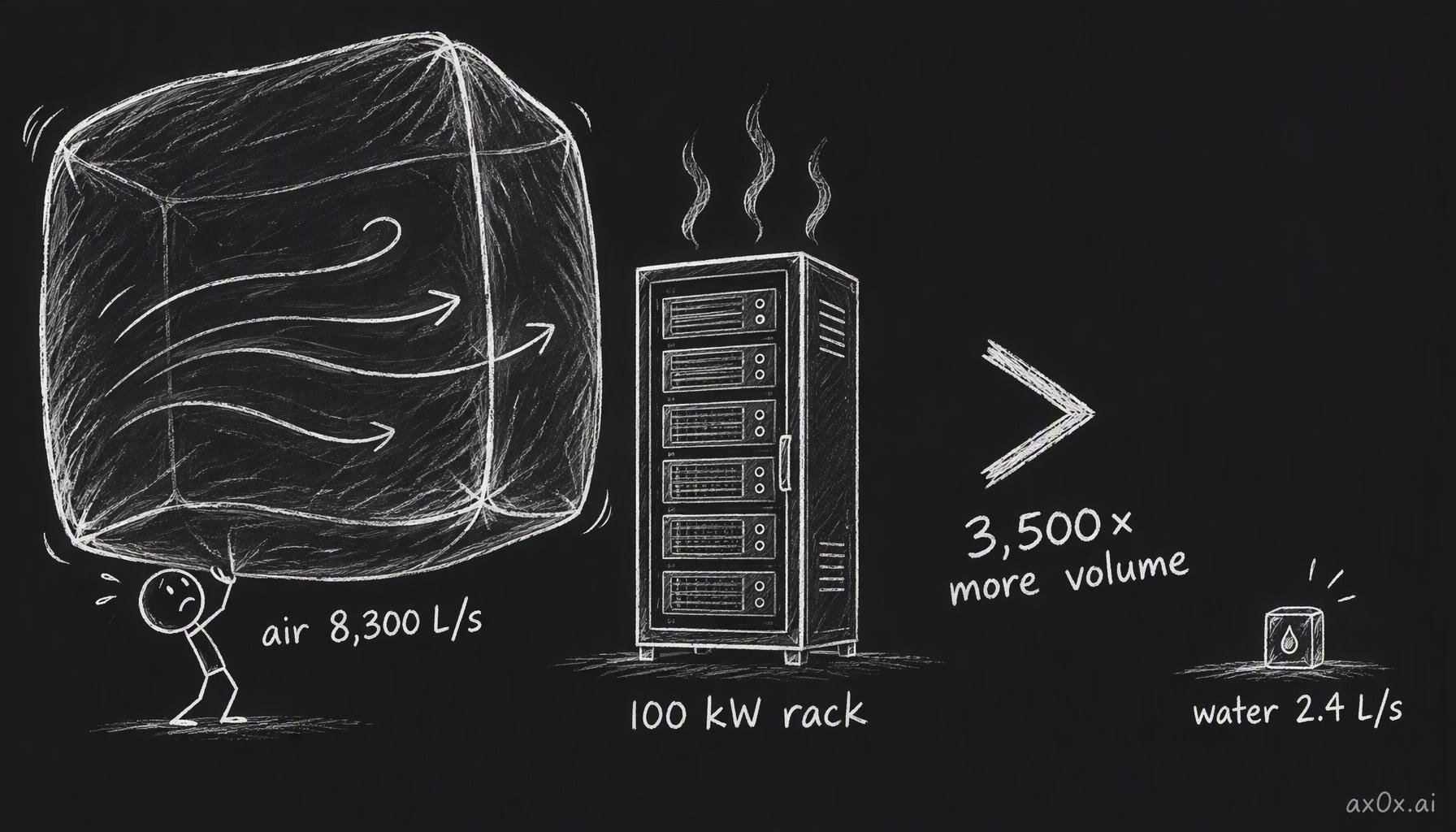 To carry 100 kW of heat with a 10 °C rise you need about 8,300 liters of air every second, or about 2.4 liters of water: roughly 3,500 times more volume of air
Two properties stack to make the gap. Water is about 830 times denser than air, so a liter of it is far more stuff. And each kilogram of water soaks up about four times as much heat per degree (about 4.18 kJ/(kg·K) for water against about 1.0 for air). Multiply the two and you get thousands.
There's a second squeeze inside the chip. Heat flux is heat per unit area. A 400 W chip spread over 4 cm² puts out 100 W/cm². Shrink the same 400 W onto 1 cm² and it's 400 W/cm², four times harder to pull out, because the heat is crammed into a smaller patch. Chips keep packing more power into each square centimeter, so cooling gets harder even when the total watts hold still.
Kian titles the chapter "Air cooling is dead" to provoke. Air still cools most of the world's IT; the accurate claim is narrower. Air alone can't handle 100 kW-class AI racks. Uptime Institute says liquid typically takes over above about 50 kW per rack, and close-coupled air (fans and coils right at the rack) tops out around there. Air also keeps a job inside liquid-cooled racks, because cold plates don't catch everything. HPE lists its GB200 NVL72 rack at 132 kW, of which 115 kW goes into liquid and 17 kW into air. Kian's teaching version is a 100 kW rack with 85% captured by the plates and 15 kW left in the room, handled by a 20 kW room air handler with 5 kW to spare.
That 15 kW can be dealt with two ways. One is a CRAH (computer room air handler), the big room unit that pulls warm air across a water coil. The other, which Kian finds the more interesting answer, is a rear-door heat exchanger: a liquid coil on the back of the rack, much like a car radiator, that catches the warm exhaust before it ever reaches the room and sends that heat out through liquid too. Vendor reference designs for GB200 NVL72 pair direct-to-chip cooling with exactly that kind of door.
The extreme option is immersion: the whole server sits in a dielectric fluid, one that doesn't conduct electricity. Single-phase keeps the fluid liquid; two-phase lets it boil on hot parts and condense above. Kian thinks immersion matters less for big AI halls, and the two-phase kind has a concrete problem: it mostly ran on fluorinated fluids such as 3M's Novec, and 3M exited PFAS manufacturing at the end of 2025.
Two loops and the box between them
A liquid-cooled rack doesn't run building water across the chips. It runs two separate loops. The inner one, the technology coolant loop, is a small, clean, tightly controlled circuit that touches the electronics. The outer one, facility water, carries heat out of the hall. Between them sits a CDU, a coolant distribution unit: a liquid-to-liquid heat exchanger where the hot inner loop hands its heat to the cooler outer loop. The two fluids never mix. Keeping them apart keeps facility grit and chemistry away from the plumbing above the GPUs.
On the chip side, the inner loop runs through cold plates, metal blocks clamped onto each GPU with channels inside for coolant. In a GB300 rack the plates are copper (suppliers describe nickel-plated copper), because copper moves heat well. Each plate hooks into the manifold through quick disconnects, so a single plate can come off for a leak or a swap without draining the whole rack. In a photo Kian shows from Abilene, the supply and return headers run along the tops of the racks, blue for cold and red for hot.
The CDU's headline spec is its approach temperature: the coolant it sends to the chips minus the facility water it receives. A perfect heat exchanger would get the two to the same temperature, an approach of zero. Real ones run a few degrees, and vendor ratings typically say 4 to 5 °C. A smaller approach gives the chips more margin but costs more exchanger surface, more pumping, or more money. That's why datasheets quote capacity "at X degrees approach." CoolIT's CHx2000, the course's example, is rated at 2 MW at a 5 °C approach. CoolIT started out cooling gaming PCs; Ecolab bought it in 2026.
CDUs get the same redundancy treatment as power, which Part 5 laid out for UPSs and feeds. Kian's example is a 1,000 kW heat load. Two 600 kW CDUs give 1,200 kW, which is only "N": lose either one and you're left with 600 kW against a 1,000 kW load. Three of them, 1.8 MW, is N+1. Two fully independent trains of two CDUs each, 2,400 kW for the same load, is 2N. Five nines of availability allows only about five minutes of downtime a year, and Kian expects sites chasing that to use 2N or even 2N+1 cooling.
When an N system does lose a CDU, it doesn't have to shut down. The controls can shed IT load, deferring work that isn't time-sensitive, until the remaining 600 kW of cooling is enough again. Cooling failure then shows up as slower compute instead of dark racks.
The contact matters more than the water
Here's the result in this chapter that surprised me most. Two chips, same 400 W, same 35 °C coolant. One ends up at 67 °C, the other at 83 °C, which is 3 °C over an 80 °C limit. Same water, same watts, 16 degrees apart.
The difference is thermal resistance, written Rθ: how many degrees hotter the chip has to be than the coolant for each watt that flows between them. ΔT = P × Rθ. At 0.2 °C/W, pushing 100 W across needs the chip 20 °C above the coolant. In the two-chip example, the first chip's path has 0.08 °C/W, so 400 W needs a 32 °C gap and the chip sits at 67 °C. The second has 0.12 °C/W, a 48 °C gap, and lands at 83 °C.
Kian describes Rθ as a property of the GPU, but it really belongs to the whole path the heat travels: the die, the thermal paste or pad between die and lid (the thermal interface material), the lid, the cold plate, and how the coolant flows over it. That's his own conclusion in different words. A chip that was mounted a bit badly, with a thin gap or a dry patch of interface material, runs hot no matter how cold you make the water.
Flow is the other lever, and the equation says how it behaves. Put 100 kW into water moving at 2.5 kg/s and it warms by 9.57 °C, from 35 to about 44.6. Double the flow to 5 kg/s and the rise halves to about 4.8 °C, because twice as much water is sharing the same heat. Specific heat changes only if you change the fluid, and the common water-glycol mixes carry slightly less heat than water.
More flow costs pressure, roughly with the square: double the flow, about four times the pressure drop. That sets a trap for anyone reading gauges. A pump delivers less pressure as flow rises, the loop demands more, and the system settles where the two curves cross. If a filter clogs or minerals scale up a valve, the loop's curve gets steeper and meets the pump's curve at a new point: lower flow, higher pressure. Kian's numbers: 2 L/s at 120 kPa becomes about 1.4 L/s at 140 kPa. The gauge reads higher and looks healthier while less water is moving. So you watch flow, not pressure.
The worst version of this is when everything at the plant looks fine. In Kian's exercise, the plant sends out coolant at a normal 30 °C. Row B gets that same 30 °C water, but a restriction has cut its flow in half, from 100 to 50 kg/s. Its return water climbs from 35 to 40 °C, and the hottest chip in the row reads 85 °C against an 80 °C limit. When the flow drops, the heat carried away drops sharply at first; the hardware stores the difference and heats up, and as the chip gets hotter it drives more heat into the slower water, until heat removed climbs back to match heat produced. The row reaches a new equilibrium. It's stable, and it's too hot. A plant supply temperature that hasn't moved tells you nothing about that row. You need flow per branch and temperature at the chip.
Getting the heat off the site
The last step dumps the heat outdoors, in one of two basic ways.
Dry cooling runs the warm water through a coil, like a car radiator, and blows outside air across it with fans. Add a compressor and refrigerant for headroom and it becomes a chiller. Wet cooling sprays the warm water over "fill," a plastic lattice designed to give the water as much contact with air as possible, so some of it evaporates. Evaporation carries off a lot of heat, and the water that's left comes back much cooler.
To see when each works, you need two temperatures. Dry-bulb is the ordinary air temperature on a shaded thermometer. Wet-bulb is what a thermometer reads with a wet cloth wrapped around it and air blowing past: evaporation cools it below the dry-bulb, the way sweat cools skin. The two are equal only at 100% relative humidity, when nothing can evaporate. On a dry 35 °C day the wet-bulb might be 22 °C; in humid air at the same 35 °C it could be 28 °C. Dry-bulb is the floor for a dry cooler. Wet-bulb is the floor an evaporative system can approach.
Kian's worked example shows the dry cooler losing. The rack loop runs hot at 55 °C. Facility water comes back from the outdoor coil at 40 °C and, through the CDU with its 5 °C approach, cools the rack coolant to 45 °C. But the chips need 35 °C coolant. On a 35 °C day a purely dry cooler can't make water colder than the outside air, and since real heat exchangers are imperfect, it can't even reach 35. Dry cooling alone can't hold full throughput that afternoon.
One fix keeps the loop closed and spends water outside it. This is adiabatic assist, which Kian compares to hitting the nitrous in a racing game. Incoming air passes through wetted pads (or a fine spray) before it reaches the dry coil. Water evaporates into the air and pulls its temperature down toward the wet-bulb, so the coil sees air several degrees cooler than the day. In pad designs the coil itself stays dry, and the water is only used on hot days.
The full wet tower needs an extra heat exchanger between the facility loop and the open tower water, which makes three water circuits: rack, facility, tower. With a 28 °C wet-bulb, the rack still can't get 35 °C water, because each exchanger adds another approach gap on top of the tower's own. At a 22 °C wet-bulb it can, and the GPUs run at full load. Wet towers also need makeup water to replace what evaporates, plus blowdown: draining mineral-heavy water on purpose, since scaled pipes quietly cut flow.
Chillers bring their own accounting. The compressor's electricity turns into heat too, so if 10 MW leaves the racks and the compressor draws 2 MW, the outdoor side has to reject 12 MW. In cold weather a plant can switch to economizer mode: compressor off, only fans and pumps running. The compressor is the largest power draw in the cooling plant, so this is where most cooling electricity gets saved.
How much heat a compressor moves per unit of electricity is its COP, coefficient of performance. A COP of 4 means one unit of electricity moves four units of heat, which works because the compressor moves heat rather than making cold. The catch is that COP falls as the outdoor side gets hotter, because the compressor has to push heat further uphill. Typical full-load COP runs about 2.5 to 3.7 for air-cooled chillers and about 4 to 6.5 for water-cooled ones.
Put that next to a fixed power cap and you get Kian's best example. A site has a 10 MW grid limit and 8 MW of IT load. On a cool day, at a COP of 8, cooling takes 1 MW and everything fits. On a hot day the COP drops to 4, cooling takes 2 MW, and with 0.4 MW of pumps and other auxiliaries the total hits 10.4 MW, 400 kW over the cap. The only lever left is the IT load: cut it to 7.68 MW and the 1.92 MW of cooling plus auxiliaries fits under 10 MW again. A COP of 8 is generous for a chiller at full load, so treat the numbers as an illustration. The chain is the real point: a hotter day means a lower COP, which means more cooling power per megawatt of compute, which, under a fixed grid connection, means less compute.
The water fight is about which loop is open
Now the argument. A rack loop being closed tells you almost nothing about how much water a site uses, because the rack loop isn't the one touching the sky. To judge water, list the loops and ask which ones are open. A dry-cooler setup has a closed rack loop, a closed facility loop, and a dry cooler that evaporates nothing. A wet-tower setup can have the exact same closed rack loop and then evaporate water all day at the end of the chain.
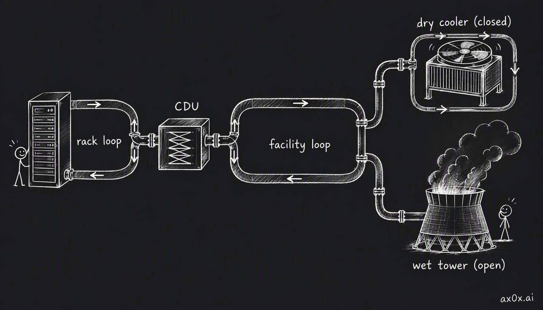 Heat leaves through loops in a row: the sealed rack loop hands off at the CDU to the facility loop, which ends at either a dry cooler that evaporates nothing or a wet tower that is open to the air and evaporates water
There's a real case of the second kind. An xAI engineer told Governing in March 2026 that Colossus in Memphis has a closed loop that never needs replacing, while its open loop needs about 3 million gallons a day.
Abilene is the course's example of the first kind. Crusoe says the site uses closed-loop facility water and rejects heat through air-cooled chillers, with no water consumed for heat rejection. "No water" still has an asterisk: Crusoe says each of the eight buildings needs about a million gallons to fill once, from municipal supply, then about 50,000 gallons a year for maintenance, by its own projection. Crusoe also says this design is rarely used at this scale because it costs more over its life, and that it chose to bear that cost for responsible water management.
Kian reads that as half-greenwashing. His take: water-cooled chillers in Texas would have drawn public backlash, and depending only on electricity may simply be the cheaper long-run bet, because in a world full of data centers competing for water, water is the scarce input while electricity can come from many sources. He invites people to disagree. One fact belongs next to his reading: air-cooled chiller plants spend more electricity, roughly 1.5 kW per ton of cooling against about 0.85 for a typical water-cooled plant. Saving the water is paid for on the power bill, and on a site like the one in the last section, power is what caps compute. Microsoft made the same trade: since August 2024 its new designs use closed-loop chip cooling filled once at construction, which it says avoids more than 125 million liters of water per data center per year.
Kian also calls "data centers are using all the water" patently false. I think that holds for sites built like Abilene and fails for evaporative sites like the Colossus example, so the honest version is scoped to the design. Two broader numbers help with proportion. About 80% of the water the U.S. actually consumes goes to agriculture. And Lawrence Berkeley National Lab estimated that U.S. data centers used about 17 billion gallons of water directly in 2023, against about 211 billion gallons consumed indirectly by the power plants generating their electricity. For many sites, I suspect, the bigger water draw is upstream, at the power plant, which makes the dry-versus-wet choice partly a choice about where the water gets spent.
Heat can also go somewhere useful. Kian's sketch is a site making 4 MW of heat around the clock that sells 2 MW to a hospital from midnight to 6 a.m.; the rest still goes outdoors. Real versions exist at city scale. Fortum started taking heat from Microsoft's data centers in Espoo and Kirkkonummi, Finland, in May 2026, and expects them eventually to cover about 40% of the area's roughly 2 TWh a year of district heating for 250,000 users. Even there, only about 75% of the waste heat gets used over a year, because nobody needs much heating in summer.
When cooling is the part that fails
The last lesson is about dependencies. Downtown Toronto is cooled by cold water drawn from Lake Ontario: Enwave's Deep Lake Water Cooling pulls water at about 4 °C from 83 meters down, through pipes running about 5 km offshore, and serves more than 80 buildings, data centers among them. The same lake water continues into the city's drinking supply, passing heat exchangers on the way, and the two systems never mix.
One of those buildings is 151 Front Street West, Toronto's main carrier hotel, with more than 150 telecom and data center tenants including the Toronto Internet Exchange. On the evening of July 8, 2013, a storm dropped 126 mm of rain in about 90 minutes and cut power to about 300,000 Toronto Hydro customers. The building switched to generators, and the racks stayed powered. But the chilled water the building depended on came from a provider that had its own power problems. Parts of the building lost cooling, server rooms ran hot, and Enwave brought in an emergency chiller. In the account Kian cites, operators shut down non-essential gear and moved workloads out of a suite that passed 43 °C. Backup power covered the racks; it didn't cover the outside water those racks needed to stay cool.
Google's europe-west2-a zone in London is the newer version of the same lesson. On July 19, 2022, during extreme heat, several redundant cooling systems failed at the same time, and Google powered down part of the zone on purpose to keep servers from being damaged. Google's report tied the failure to extraordinarily high outside temperatures; redundant units that share the same weather can fail together.
Both stories fit Part 5's point that the baton drops at the handoffs. The cooling plant is one more runner, with its own power and water supply.
If you ever see an AI service get a little slower on a scorching afternoon, this chapter offers one possible reason. On a site whose grid connection is fixed, a hot day lowers the chillers' COP, cooling eats more of the power budget, and the operator may have to trim compute to stay under the cap. I can't tell you that's what happened on any given day, but the arithmetic says power-capped sites should feel the weather.
Next: The GPU-Hour Ledger, where all of this turns into contracts, and electricity turns out to be a small line on the bill.
This series is compiled from Kian's (@neuralkian) freeCodeCamp course "Inside an AI Factory – Power, Cooling, and GPUs Explained" (originally titled From Watts to Tokens; course notes at kiankyars.github.io/gigawatt). The framework and most examples are Kian's; I reorganized it by theme and re-checked the numbers, so any errors are mine. Companies are named only as examples, and nothing here is investment advice.