
From 345 kV to One Volt
The electricity feeding a large AI campus arrives at hundreds of thousands of volts. The silicon at the far end of the chain runs at about one volt. Every transformer, switchboard, busway, power shelf and voltage regulator in the building exists to take one step down that staircase. The power stays roughly the same on the way down, minus losses. So each time the voltage drops, the current goes up, and the heat wasted in the copper grows with the square of that current. Double the current and you get four times the heat.
My reading of Kian's course is that nearly every electrical headache in an AI data center lives in that gap between falling voltage and climbing current. A busway that trips with empty slots still on it, a transformer overloaded by power that does no work, a sliver of copper beside a GPU that, in Kian's worked example, wastes 100 W by itself: all of them come from current. The industry's big shift follows from the same fact. Running 800 V DC into the rack is the grid's oldest trick (carry power at high voltage and low current for as long as you can), moved from the transmission line to a few centimeters from the chip.
The staircase starts at 345 kV
The previous part was about getting power to the site at all. This one follows it inside. The course's running example is Stargate's campus in Abilene, Texas. Mortenson, the electrical contractor, describes the phase-2 substation as a 1 GW, 345 kV greenfield station with five main power transformers. The first transformer was energized on December 19, 2025, and the whole station by March 10, 2026. Phase 1 had been a smaller 200 MW station at 138 kV.
From 345 kV, Kian's slide steps down ten to one, to 34.5 kV. That is a standard US medium-voltage level for big campuses, though the public record doesn't confirm that exact figure for Abilene. In the typical US layout, medium voltage runs across the campus to each data hall, where a second transformer takes it to 480 V three-phase, the usual US low-voltage level. The racks hang off that 480 V network, and so do the cooling pumps. Kian makes a point of the pumps. If they lose power, the GPUs overheat even while their own feed is perfectly healthy.
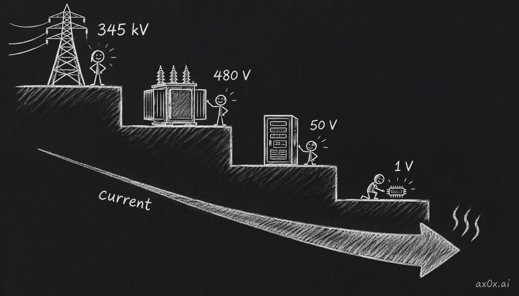 The voltage staircase: power arrives at 345 kV and reaches the chip at about 1 V; each step down raises the current, and resistive heat grows with its square
Between the transformers sits switchgear: cabinets of breakers, relays and bus bars. It has two jobs. Protection means sensing a fault, such as a short or a lightning surge, and opening a breaker before the surge reaches expensive equipment downstream. Distribution means splitting the supply into feeders, one per hall, so each hall can be switched on its own. A campus built in phases installs feeders for halls that don't exist yet and leaves them dead until those halls are finished. Abilene shows the scale of that phasing: a campus planned at about 1.2 GW started life with a 200 MW first phase.
Why not step down to 480 V at the gate and save the second transformer? Because of the current. Two megawatts at 480 V three-phase is about 2,400 A. Low-voltage, high-current runs are heavy on copper and heavy on heat, so the rule is to transmit high, distribute across the campus at medium voltage, and drop to low voltage right beside the hall. The fat-current leg stays as short as you can make it. Almost everything later in this article is that same rule applied at a smaller scale.
These boxes are also the slow part of a build. Big power transformers take two to four years to arrive, and switchgear a year or more. Developers have started working around the queue. Crusoe makes its own medium-voltage switchgear, low-voltage switchboards, enclosures, controls and copper busbar in Tulsa, Oklahoma. Its second plant there opened on September 14, 2026. Crusoe says it has shipped more than 2,500 switchboards to Abilene and turns around in days what the industry takes months to do. It doesn't make transformers. Siemens took a different route with Compass Datacenters: a December 2024 agreement for up to 1,500 factory-tested skids over five years, each combining Siemens 8DJH 36 gas-insulated switchgear with transformers, with the first deployment projected for the second half of 2025 near Chicago. The idea is to move integration work off the construction site and into a factory, where the unit is tested before it ships.
Three-phase power and the budgets that trip you
Engineering drawings show a 480 V circuit as a single line. Physically it is five conductors: three live phases, each offset by 120 degrees, a neutral, and a protective earth.
The reason for three phases is smoothness. A single AC phase delivers power in pulses, dipping to zero twice per cycle. Add two more phases offset by a third of a cycle each, load them evenly, and the dips of one are filled by the others. The total power flowing into the load is constant at every instant. GPUs and their power supplies want steady power, and three-phase is the cheapest way to move a lot of it smoothly.
Then comes a puzzle that catches most people. If each phase is 480 V, why don't two of them make 960 V? The answer is that 480 V is measured between two phases, and 277 V is measured from any phase to neutral. The voltage between two phases is the difference between two waves that sit 120 degrees apart, and that difference works out to √3 × 277 V, which is 480 V.
The 277 V figure matters inside the rack. GB300's power supplies are single-phase units rated for 200 to 277 V AC, so each one sits between one phase and neutral. A shelf of six spreads them two per phase. In Kian's worked example, each phase has a 60 A limit and each group of supplies draws 20 A. Spread them evenly and everything fits. Put four groups on one phase and that phase carries 80 A while the other two carry 20 A. The rack's total demand is fine; one phase still trips.
The same arithmetic shows up one level higher, in the busway. Many halls feed racks from overhead: a long copper bar runs along the row, an end feed powers the whole run, and tap-off boxes take protected branches down to each rack. Kian's example is a 250 A end feed at 415 V with 40 kW racks, which comes to about 55.6 A per rack. Four racks draw 222.6 A. A fifth pushes the total to 278.3 A, 28.3 A over the feed, even though the busway still has open tap-off slots. How many racks a busway can carry is set by its end feed, and the number of slots says nothing about it.
Power factor is the last budget at this level, and it's a sizing problem more than an efficiency one. Motors, transformers and capacitors store energy in their magnetic and electric fields every AC cycle and hand it back. That energy does no work at the load, but it still travels as current through the wires. Engineers split power into real power (kW), which does the work, and apparent power (kVA), which is what the cables and transformers actually have to carry. Power factor is the ratio between them. Kian uses a meme of a pint of beer: the liquid is real power, the foam is reactive power, the whole glass is apparent power. The picture is useful even though the meme's percentages aren't.
His worked example is the one to remember. A 900 kW load at 480 V draws about 1,083 A at power factor 1. On a 1,000 kVA transformer that is 90% loaded. At power factor 0.9 the same 900 kW sits exactly at the transformer's limit. At 0.8 it needs 1,125 kVA, 12.5% over, and the current rises to about 1,353 A. A low power factor doesn't mean a slice of the energy is thrown away. It means more current for the same work, which needs bigger equipment and heats the copper more. DC has no power factor on its own side, which Kian lists as one reason for the shift to DC. The rectifiers that turn AC into DC still present a power factor and harmonics to the AC grid upstream, so the AC side still has to be sized for it.
From the rack door to one volt
Inside the hall, the chain gets short and dense. A floor PDU (power distribution unit) spreads the feeders across the hall. A rack PDU hands AC to the outlets in one rack. The power shelf, a row of power supplies, is where AC finally becomes DC. On a GB300 NVL72 that DC lands on a vertical busbar at 50 V nominal, allowed to wander between 47.5 and 51.5 V. Lenovo puts the rack at about 135 kW typical with peaks around 155 kW, fed by eight shelves of six 5.5 kW supplies. That's 264 kW installed against about 135 kW of typical draw, the redundant configuration, so a failed supply can be swapped while the GPUs keep running. Part one walks through the rest of that rack.
Each conversion costs something, and Kian shows how engineers size a rack feed by working backward from the chips. In his example, 72 kW of processors behind voltage regulators that are 92% efficient need 78.26 kW. Add 12 kW for memory, networking and fans, and the DC bus carries 90.26 kW. Divide by 97% power-supply efficiency and 93.05 kW enters the rack. About 9 kW of that is lost in the two conversions alone, and in the end every watt, used or lost, leaves as heat, which is part seven's problem.
Now the last inch. A 1 kW chip at 1 V draws 1,000 A. Suppose the copper path from the regulator to the die has a resistance of 100 micro-ohms, a ten-thousandth of an ohm. At 1,000 A that path drops 0.1 V, so the regulator has to put out 1.1 V to deliver 1.0 V, and the path itself burns 100 W, a tenth of the chip's power. Cut the resistance to 10 micro-ohms and the regulator only needs 1.01 V, with 10 W lost. At this current, tiny resistances turn into large losses, so the final conversion has to sit right up against the die.
Kian calls the routes there "all roads lead to Rome." One design converts straight from 51 V to 1 V beside the chip, which needs only about 20 A coming in for a 1 kW load. The other adds an intermediate 12 V rail across the board, carrying about 83 A, and makes the final step from 12 V to 1 V at the chip. Splitting the conversion gives more freedom in picking regulators and laying out the board. Meta's published OCP spec for its GB300 compute tray, effective September 4, 2025, takes the second road: a 51 V rack input that tolerates anything from 46 to 52 V, 48 V to 12 V converters on the tray's power board, then the last step to about 1 V. Kian recommends the spec as further reading.
The final step is done by the VRM, the voltage regulator module. Each VRM phase is a buck converter: two transistors switching very fast and an inductor (the coil engineers call a choke) that resists changes in current and keeps it flowing smoothly between switching pulses. A single phase supplying 1,000 A would ripple badly and make the chip's voltage wobble. So designers run several phases in parallel and stagger their timing, and the ripples partly cancel. Kian illustrates it with four phases of 250 A each; real GPU regulators use many more. That's why a photo of a GPU board shows the chip ringed by chokes, and why the CPU next to it, drawing far less power, has only a few.
One thing sits even closer to the GPU than its regulators: HBM, the stacked memory. The reason is bandwidth, along with the I/O power and signal quality of a very wide, very short connection, which How HBM Works explains. Kian reads the placement as a priority order on the package: memory first, power delivery second, everything else further out. Optics runs on a similar logic, keeping the lossy electrical segment as short as possible, which is the story of the packaging war.
Racks are outgrowing 50 volts
All of this works at today's rack sizes. The problem is how fast the racks are growing. A typical enterprise CPU rack draws under 10 kW and rarely more than 15 to 20 kW; in Uptime Institute's 2026 survey, about 69% of operators said their typical rack is under 10 kW. GB300 NVL72 is already at about 135 kW. Vera Rubin NVL72 is reportedly around 190 to 230 kW, according to supply-chain estimates rather than NVIDIA. Jensen Huang put the Kyber rack (Rubin Ultra NVL576) at about 600 kW at GTC 2025, with a target of the second half of 2027. SemiAnalysis reported in July 2026 that Kyber may slip to 2028 because its midplane board is hard to manufacture; NVIDIA says its roadmap is intact. Further out, Bank of America projects Feynman-era racks at 1.5 MW or more, a figure known only through press summaries of its note.
The busbar is where 50 V runs out. NVIDIA's own numbers make the case plainly. Its developer blog says 54 V rack distribution hits physical limits above about 200 kW per rack, and that a 1 MW rack at 54 V would need up to 200 kg of copper busbar, which across a 1 GW site adds up to as much as 200 tonnes. Space goes the same way. A GB300 NVL72 already spends up to eight slots on power shelves, and NVIDIA says 54 V shelves at Kyber's scale could take 64U of rack space.
800 V DC is the grid's trick, moved indoors
The answer the industry has landed on is to keep the voltage high until much closer to the chip. Kian's comparison uses 100 kW. Delivered as 480 V three-phase AC, it needs about 120.3 A on each of three conductors. Delivered as 800 V DC, it needs 125 A on each of two. (To match the AC current exactly you'd need about 831 V.) Give each conductor a resistance of 10 milliohms: the AC version loses about 434 W and the DC version 312.5 W, roughly 28% less. The loss falls because two conductors now carry about the current that three used to carry, and the copper saving is a consequence of that. Kian frames it as a third fewer current-carrying conductors. NVIDIA's own claim is about 45% less copper than 415 V AC.
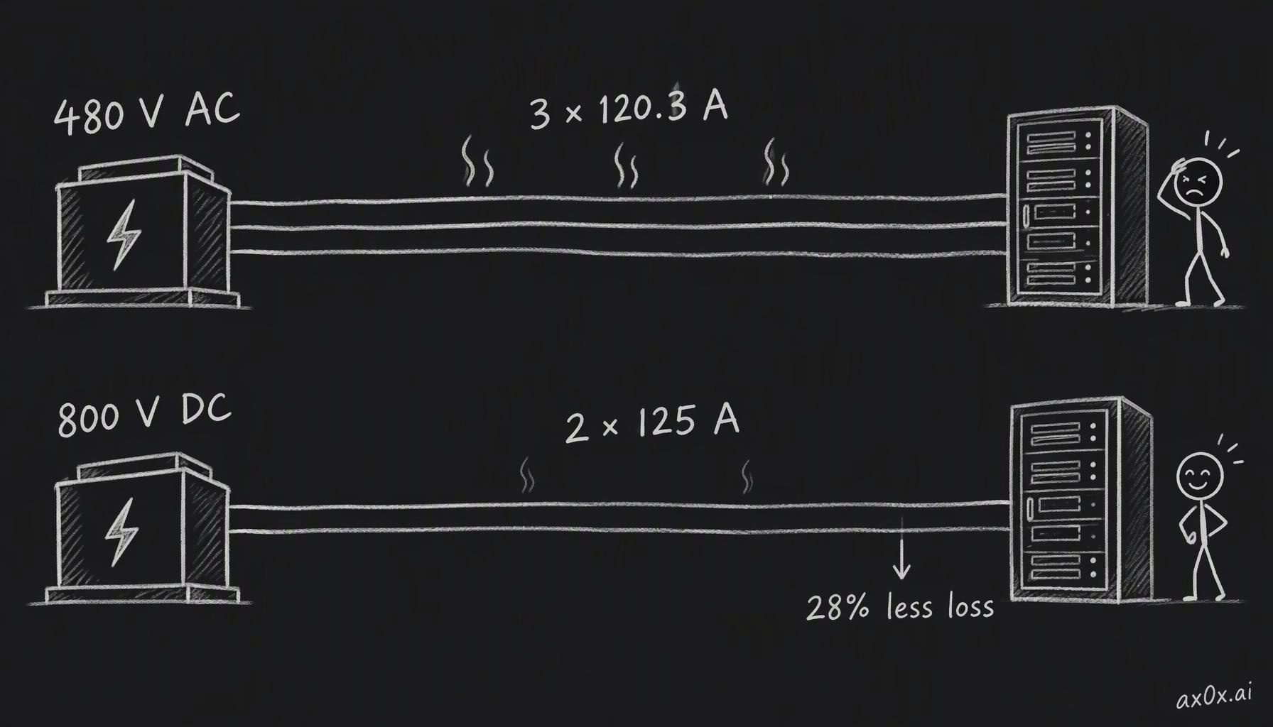 Delivering 100 kW: 480 V three-phase AC needs about 120.3 A on each of three conductors, 800 V DC needs 125 A on each of two, and the DC run loses roughly 28% less to resistance
NVIDIA announced its 800 V DC architecture in 2025, aimed at "1 MW IT racks and beyond, starting in 2027." It claims up to 5% better end-to-end efficiency and up to 70% lower maintenance cost than 54 V systems; those are NVIDIA's figures. Kian treats the rack-space argument as the main takeaway. Once AC-to-DC conversion leaves the compute rack, the space the power shelves took can hold more compute trays or switches.
The rollout comes in three steps. NVIDIA's 2026 spec, as reported by StorageReview, describes them as options. Option A puts a sidecar, a separate power rack beside the compute racks, that converts 415 or 480 V AC into 800 V DC, with production in the third quarter of 2026. Option B moves conversion into centralized power centers feeding 800 V DC row busways, in the third quarter of 2027. Option C does the conversion at hall level, with 4.8 MW DC power blocks and solid-state transformers, around 2029. Vertiv expects 800 V-native designs to become the norm around 2028 to 2029. In Kian's telling, the compute rack itself is the same whether it is fed by a sidecar or by hall-level DC. The sidecar exists so vendors can ship the all-DC rack before the hall around it is rebuilt.
The standards picture is converging but not settled. An OCP post in August 2026 described Google, Microsoft and NVIDIA converging on 800 V DC, with more than 80 partners building equipment. The bridge is Mt. Diablo, a ±400 V DC sidecar spec from Meta, Microsoft and Google whose v1.0.0 took effect on October 8, 2026, built to support current racks; a Mt. Diablo 2.0 is planned for native 800 V.
Inside the rack there's a second choice. You can convert 800 V down to about 50 V at the rack entrance and keep today's busbar, which is compatible with everything already built. Or you can run 800 V down the busbar itself and convert at each tray, which loses less and packs more power into the space. Delta has reportedly shown a 90 kW 1U shelf that converts 800 V to 50 V for the first option.
Retrofits have their own arithmetic. In Kian's example, an existing row has an AC allocation of 240 kW. You want to hang two 120 kW DC racks off a sidecar that is 96% efficient and needs 3 kW for its own fans and controls. That requires 253 kW of AC, 13 kW over the allocation. Trim the racks to 110 kW each and the requirement drops to 232.17 kW, leaving 7.83 kW of headroom. The hall also stays partly AC no matter what, because cooling and ordinary building loads still run on AC.
None of this is a new idea. In May 2012, ABB and Green Datacenter opened a data center at Zurich-West running a 1 MW, 380 V DC distribution system. ABB reported 10% better efficiency and 15% lower capital cost than AC, both vendor claims. Kian's point about it is that it was bespoke, built around its own DC voltage, so its parts didn't work anywhere else. Standardizing on 800 V is meant to fix that.
What DC makes harder
DC has costs, and Kian lays them out alongside the benefits without declaring a net verdict.
The first is arcs. When a breaker opens under load, current can keep flowing across the gap through hot ionized gas. In AC, the current crosses zero twice every cycle, and at each zero the arc has a chance to die. DC never crosses zero, so an arc can persist until the source is cut or the contacts are pulled far enough apart. A DC breaker has to force the current to zero itself. In a DC circuit the rectifiers, capacitors and inductors can all feed energy into a short, and the breaker has to stop that and then hold off the voltage afterward. The industry's toolkit includes solid-state breakers that clear in milliseconds, DC fuses, arc-fault detection, insulation monitoring and interlocked connectors, with standards work under way at UL, NFPA, IEEE and IEC.
The second is that DC stays live. Isolate the AC side of a DC system and batteries and capacitors still hold the DC link up. Before anyone works on it, the battery has to be disconnected and the link discharged. Kian's analogy is a closed water pipe: no flow doesn't mean no pressure.
The third is a bet rather than a cost. The conventional way from medium-voltage AC to 800 V DC is an iron-core transformer down to low-voltage AC, then a rectifier. A solid-state transformer does both in one box: it rectifies first, then steps down through a small transformer switching at high frequency, so the magnetics shrink. Microsoft, Google and NVIDIA published an OCP spec for it, version 0.3, in 2026, and Siemens and Reinhausen have announced a unit that would take up to 36 kV AC straight to 800 V DC, as a development plan. Kian calls SSTs the high-variance option: possibly simpler and cheaper, with much less certainty. The field record supports his caution. The best-known early unit was a 1.2 MW traction transformer ABB piloted on one Swiss shunting locomotive, in service from February 2012, and SSTs have almost no track record in data centers. Next to transformers that every utility engineer understands, that's thin evidence. I suspect SSTs show up first where the space savings pay for the risk, and conventional transformers stay the default for a while.
When a new GPU rack is announced, I'd read two lines first: the power it needs and the voltage it expects at the rack door. Together they roughly tell you how much copper, conversion hardware and rack space sit between the grid and the chip, and as racks head from roughly 135 kW toward 600 kW, whether a hall wired for 50 V can host them at all.
Next, what happens when the power at the top of this staircase flickers: When the Power Blinks.
This series is compiled from Kian's (@neuralkian) freeCodeCamp course "Inside an AI Factory – Power, Cooling, and GPUs Explained" (originally titled From Watts to Tokens; course notes at kiankyars.github.io/gigawatt). The framework and most examples are Kian's; I reorganized it by theme and re-checked the numbers, so any errors are mine. Companies are named only as examples, and nothing here is investment advice.